Taking a TFT display assembly from an engineering prototype to a production-ready module that ships at 100K+ units per month is one of the most under-documented journeys in hardware engineering. The display itself is the easy part. It's the integration — touch bonding, cover glass, mechanical mounting, optical performance validation — where projects hit their most expensive delays.
After 15 years and 50 million units, here's what we've learned about doing it right.
Phase 1: Specification Lock (Don't Skip This)
The single most common cause of production delays we see is an incomplete specification. OEMs often arrive with a resolution and a diagonal size and assume the rest will work itself out. It won't. Before ordering prototype samples, lock these parameters:
- Brightness: Not just the nominal spec — specify the minimum acceptable brightness at end-of-life (50,000 hours) and at the extremes of your temperature range. A 1000-nit panel that drops to 700 nits after 50K hours and 500 nits at -20°C may no longer meet your sunlight readability requirement.
- Viewing direction: For TN panels, the 6:00 vs 12:00 viewing direction matters enormously. A display optimized for 12:00 viewing (looking down) will appear inverted when viewed from below. For medical carts and industrial panels where viewing angle varies, specify IPS technology.
- Touch integration approach: Will the touch sensor be a separate component (discrete), laminated to the LCD (optical bonding with OCA/OCR), or integrated on-cell? This decision cascades into thickness, optical performance, cost, and reliability.
- Cover glass requirements: Thickness, edge treatment, surface coatings (AG/AR/AF), ink printing (color, opacity, registration tolerance). Cover glass is frequently the long-lead item — start the conversation early.
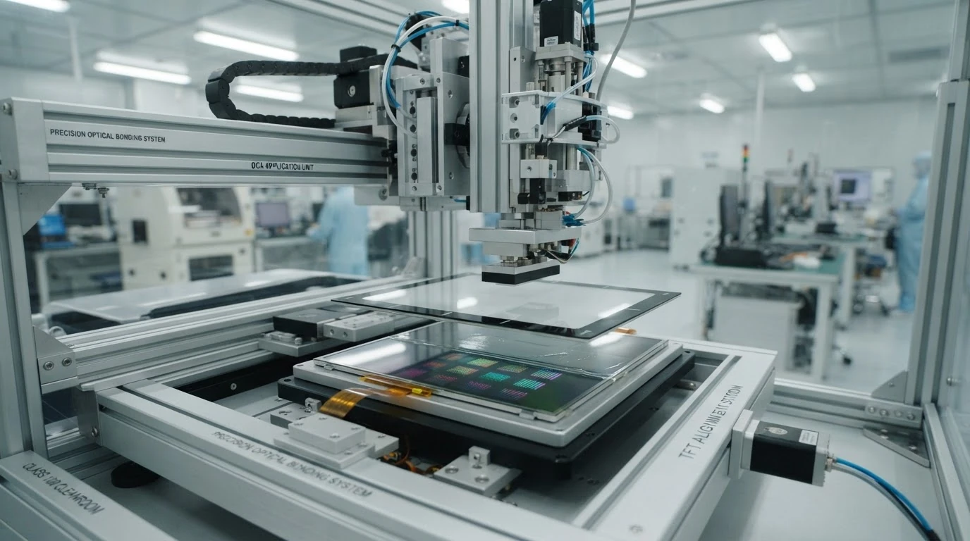
Phase 2: Optical Bonding — The Make-or-Break Step
Optical bonding — filling the air gap between the LCD and the touch sensor or cover glass with an optically clear adhesive — transforms display performance. It eliminates two reflective surfaces (air-to-glass interfaces), dramatically improving contrast and sunlight readability. It also prevents condensation and dust ingress between layers, which is a common field failure mode for non-bonded assemblies.
The two primary approaches:
OCA (Optically Clear Adhesive) film: A solid, pressure-sensitive adhesive sheet, typically 0.125-0.200mm thick. Applied via vacuum lamination. Advantages: uniform thickness, no liquid handling, faster cycle time (30-60 seconds per lamination). Disadvantages: more susceptible to bubbles on textured surfaces, higher per-unit material cost. Best for: flat-to-flat surfaces, high-volume production.
OCR (Optically Clear Resin) liquid: A UV-curable liquid adhesive applied via dispensing or curtain coating, then cured. Advantages: fills surface irregularities better, lower material cost, excellent for curved or irregular surfaces. Disadvantages: slower cycle time, requires precise dispensing control (±0.05mm thickness tolerance), more complex process control. Best for: curved surfaces, applications requiring the thinnest possible gap fill.
The decision between OCA and OCR typically comes down to surface geometry and volume. For 95% of flat industrial and medical displays, OCA film is the right starting point. At volumes above 50K/month, OCR's lower material cost may justify the more complex process.
Phase 3: Mechanical Integration — The Mounting Problem
A TFT assembly needs to survive mechanical shock, vibration, and thermal cycling while maintaining optical alignment between LCD, touch sensor, and cover glass. Key design rules:
- Never hard-mount the LCD glass directly to the enclosure. Use gaskets, foam tapes, or spring clips that allow for differential thermal expansion. The LCD glass and the aluminum/magnesium housing expand at different rates — hard mounting will crack the glass within the first 100 thermal cycles.
- Include a service loop in the FPC. The flexible printed circuit connecting the LCD to the driver board must have enough slack to accommodate assembly tolerances and thermal expansion. A 180° bend with a minimum bend radius of 2mm (for standard FPC) is standard practice.
- Design for zero-gap between touch and cover glass. Any air gap creates an internal reflective surface. If your design has a discrete touch sensor and cover glass, bond them — don't clamp them.
- EMI gasketing. TFT driver boards can radiate in the 30-300MHz range. Plan for conductive gaskets or spring fingers between the LCD metal frame and the enclosure ground.
Phase 4: Validation Testing
Before releasing to production, validate:
- Thermal cycling: -20°C to +70°C, 100 cycles, 2-hour dwell at each extreme. Inspect for delamination, LCD fluid leakage, touch calibration drift.
- High-temperature/high-humidity: 60°C / 90% RH for 500 hours. Tests the OCA/OCR bond integrity and the edge seal.
- Mechanical shock: 50G, 11ms, half-sine, 3 axes. Particularly important for handheld and vehicle-mounted displays.
- UV exposure: 500 hours UV-A. Tests cover glass adhesive yellowing and OCA/OCR UV stability.
- Touch cycle test: 1 million touches at center and edge using a 8mm silicone finger at 250g force. Verifies touch panel and bonding durability.
Phase 5: Production Ramp — Quality Gates
At EMS Display, every TFT assembly passes through four quality gates before shipment:
- Incoming QC: LCD panel inspection (dead pixels, mura, backlight uniformity), touch sensor functional test, cover glass cosmetic inspection (MIL-PRF-13830B scratch/dig standard).
- Post-bonding AOI: Automated optical inspection after lamination checks for bubbles (>0.2mm rejected), adhesive squeeze-out, and alignment error (>0.3mm offset rejected).
- Functional test: Full display pattern test (white, black, red, green, blue, grayscale ramp), touch calibration and linearity test, backlight current measurement.
- Final visual: Human inspector under controlled lighting (1000 lux) at 30cm distance, 5-second inspection per unit.
Our production yield across all TFT assembly lines averages 99.7%. The 0.3% rejection rate is almost entirely cosmetic — a visible dust particle under the cover glass, a 1-pixel shift in the ink border, a barely-perceptible mura in a corner. For medical and premium industrial customers, we hold to a zero-cosmetic-defect standard. For cost-sensitive industrial applications, we offer a graded acceptance (Class A/B/C) at progressively lower price points.
Why This Matters
The display is often the most expensive single component in a device's BOM, and the one that users interact with most. An avoidable field failure — condensation between layers, touch delamination, backlight uniformity drift — can trigger a recall that costs 10-100× the per-unit savings from cutting corners on assembly quality. The lessons above represent hard-won experience; hopefully they help you avoid the same expensive mistakes.
Planning a TFT display assembly project? Browse our TFT assembly product line or contact our engineering team for a DFM review of your design.